 English
Spiral Phased Array Antenna
The Spiral Phased Array Antenna is a Trinity Radionics antenna design based on Archimedean spiral geometry, multi-layer PCB construction, RF tuning concepts, and scalar-style subtle-energy broadcasting theory.
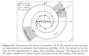
Spiral Phased Array Antenna: Concept and Technology
After extensive research and experimentation in the 5MHz to 8MHz range, Trinity Radionics developed an Archimedean multi-phase antenna intended for use as a stick pad, broadcaster, or external antenna within radionics-style signal work.
Although the antenna concept can be explored across a broader frequency range, the design was calculated and optimized around the 5MHz to 8MHz operating window. This range is used in selected Trinity Radionics designs for balancing-energy work, intention broadcasting, and subtle-energy applications.
Archimedean and Exponential Spiral Research
During development, both Archimedean and exponential spiral patterns were studied. Each spiral type has different mathematical properties, practical advantages, and design trade-offs.
Archimedean spiral arms can become long, which may introduce higher circuit losses at lower frequencies. Their wrap angle also changes from the center to the outer diameter. The inner region can excite higher-order modes at higher frequencies, while the outer region may support improved pattern behavior at lower frequencies.
Exponential spirals can offer more uniform behavior across a broader frequency range. However, for the Trinity Radionics design goal of shortwave-oriented work around 5MHz to 8MHz, the Archimedean spiral was selected as the preferred structure.
Four-Layer Spiral PCB Structure
The antenna design uses a four-layer PCB stack, with four carefully calculated spiral structures arranged across the layers.
Spiral trace width, spacing, spiral count, layer placement, and PCB stack behavior were calculated as part of the development process. The thin dielectric separation between layers creates a compact capacitive structure intended to support phased interaction inside the antenna.
This layered construction allows the antenna to function as a compact multi-phase structure for radionics-style broadcasting, stick pad use, and subtle-energy experimentation.
Feed Bridge and Capacitive Coupling
One of the most important parts of the antenna design is the spiral feed bridge. The feed bridge sits at the center of the spiral and can be configured using resistive or capacitive coupling, depending on the intended frequency range and broadcast style.
During testing, a capacitive feed bridge was selected as the preferred approach for this design. The capacitor values were calculated using relationships inspired by the Pythagorean golden ratio, φ = 1.618, with the goal of creating proportional differences between selected capacitance values.
Component selection was also important. Standard ceramic SMD capacitors did not perform as desired in this design context, so high-quality RF capacitors and mica dielectric capacitors were preferred during development.
Near-Field Phase Interaction
The Spiral Phased Array Antenna is designed around the concept of near-field phase interaction. In Trinity Radionics terminology, this means that multiple spiral layers and phase relationships are arranged to create a focused scalar-style broadcast field.
The goal is a stronger, more coherent broadcast structure for radionics work and intention broadcasting.
Design and Development Tools
The antenna design process used a combination of mathematical calculation, RF design concepts, PCB layout development, and practical experimentation.
- Frequency spectrum calculations were developed with MATLAB.
- Golden ratio and proportional capacitance calculations were developed with MATLAB.
- PCB design and blind-via layout work were developed with Altium.
- Original spiral geometry work was developed with SolidWorks.
- Final design behavior was refined through physical testing and radionics-style evaluation.
Technology Summary
The Spiral Phased Array Antenna combines:
- Archimedean spiral antenna geometry
- Four-layer PCB construction
- Multi-phase spiral layout
- Capacitive feed bridge design
- High-quality RF or mica capacitors
- 5MHz to 8MHz tuning focus
- Near-field phase interaction concepts
- Stick pad and radionics broadcaster applications
Intended Use
This antenna concept is intended for radionics practitioners, subtle-energy researchers, and users interested in spiral geometry, phase-array antenna structures, scalar-style broadcasting, and intention-based energetic work.
It may be used as part of a radionics machine, external antenna system, stick pad setup, or experimental subtle-energy broadcasting platform.
Conceptual Papers and References
The following papers and references were used as conceptual background during the development of the Spiral Phased Array Antenna design language:
-
Scalar Waves: Theory and Experiments
-
Classical Superposition of Waves to Quantum Interference
-
Mitigation Reflections from Antenna Spiral Arm Ends
-
A Systematic Approach to Improving the Performance of Spiral Antenna
-
Wideband Novel Modified Archimedean Spiral Antenna Array
Important Notice
Trinity Radionics antenna content is provided for radionics, symbolic, educational, and personal practice purposes. These antenna designs are not medical devices and are not intended to diagnose, treat, cure, or prevent any disease. Scientific and technical references are included as conceptual background and should not be interpreted as clinical proof or guaranteed physical effects.